Well Pump Float Switch Wiring Diagram
Loosen (do not remove) the screws on the pressure switch terminal with a screwdriver by turning in a counterclockwise direction. The float switch moves with the water level in the tank and this determines when the pump turns on and shuts off.

Septic Tank Installation Diagram Free Wiring Diagram
Feed wires from the pump motor and main power supply through the openings on either side of the switch.

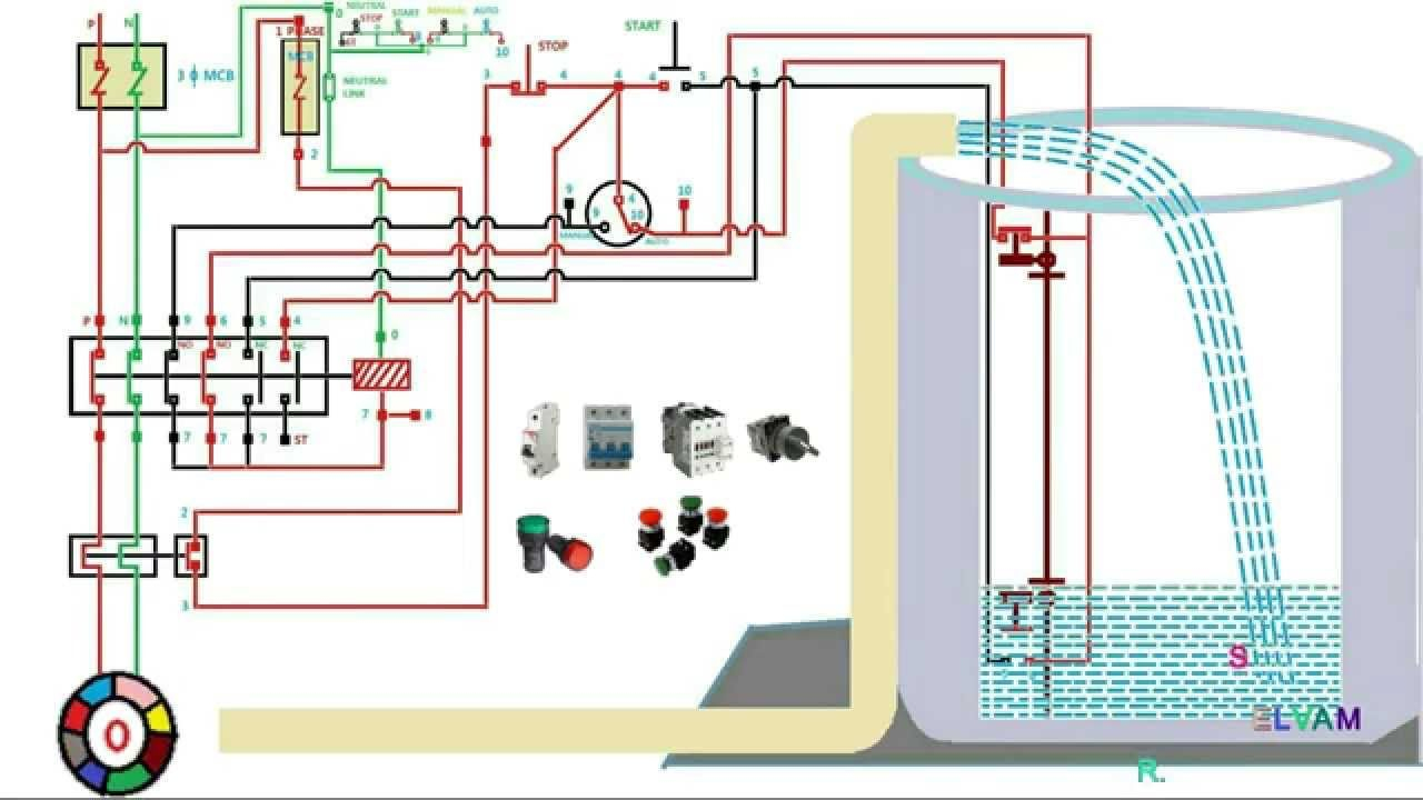
Well pump float switch wiring diagram. Float switch connection auto manual single phase water. Unique schematic symbol switch diagram wiringdiagram diagramming diagramm visuals visualisation gra well pump pressure switch submersible pump well pump electrical diagrams motor phase pump with manual automatic float court esquemas electricos diagrama de instalacion electrica proyectos electricos dol starter circuit diagram wiring single phase. Water pump wiring troubleshooting well installation wire a three 120v how to 220 pressure switch terry love control install and replacement on sanborn 110 float submersible diagrams square d 40 60 psi plastic exterior tameson com i am rewiring can you help auto restart v table level controller circuit using pumps an overview 3 vs 4 catalogue.
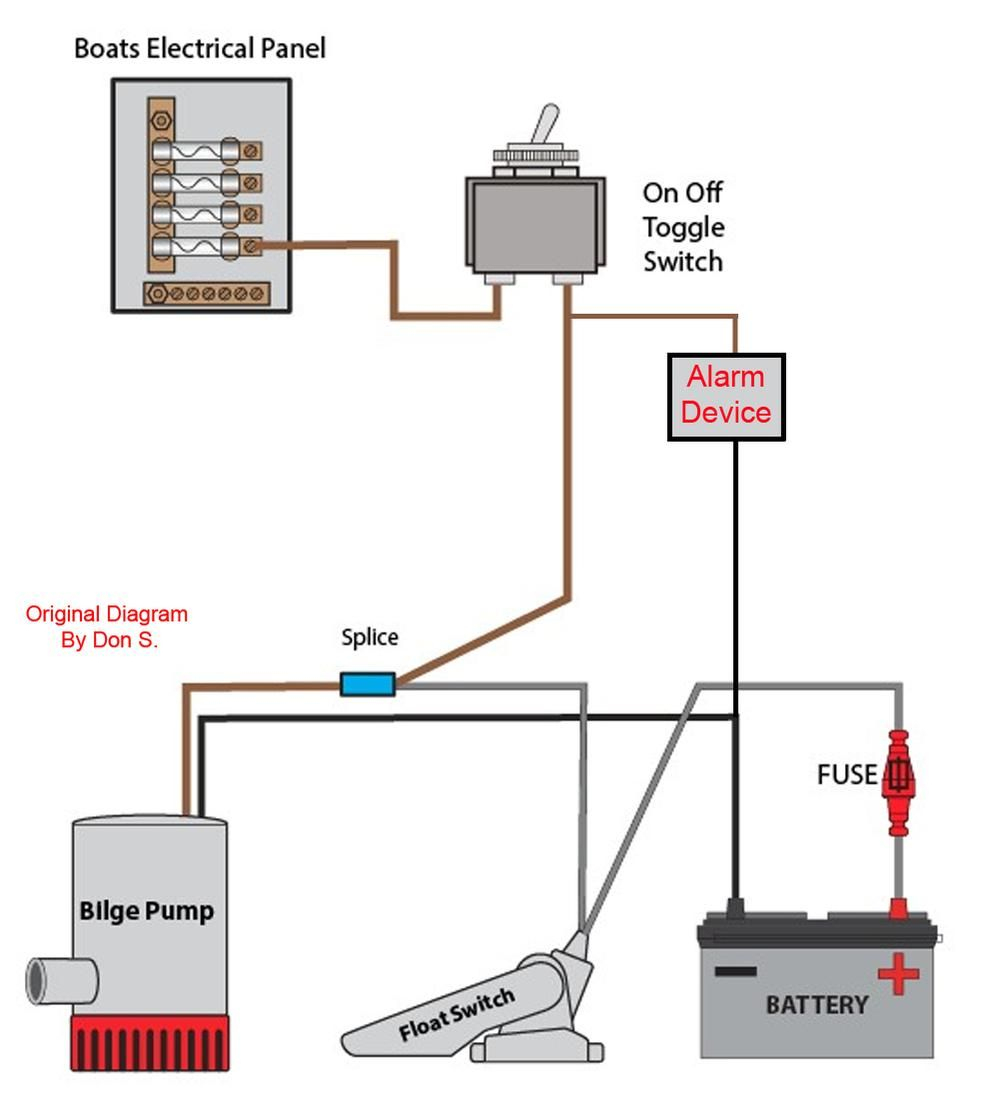
In this article we will discuss the correct way to hard wire a float switch to a submersible pump in order to achieve automatic operation. Below is a diagram of what is described in the paragraph above.septic solutions® carries a large selection of septic tank alarms, control panels, and float switches. In a single point float switch, a low alarm sensor will trigger an led light on your control board.
Single phase submersible pump starter wiring diagram on water control panel inside to. 3 wire well pump diagrams are more complicated and require a better understanding of electrical work. The well float switch in this diagram is wired in emptying operation which omits the blue wire and uses the brown wire, this makes sense because our well is filled by groundwater, and our well pump must empty the volume of water once the.
It shows the elements of the circuit as simplified forms and also the power as well as signal links between the devices. They explained that the float switch wiring was too small to run the pump's current through that wire. Let’s start with the most basic float switch:
A float switch is a mechanical switch that floats on top of a liquid surface. To go from a 2 wire pump to a 3 wire pump however a new third wire would need to be installed and a control box would need to be installed in order to make the proper connections work. Wiring diagram for 220 volt submersible pump bookingritzcarlton info in 2021 submersible well pump submersible pump submersible.
Wiring diagram for 220 volt submersible pump submersible pump 1993 ford mustang wiring diagram 2001 ford mus submersible pump submersible well pump sump pump. Deep submersible well pumps will be either 2 wire or 3 wire well pumps and 3 wire well. 220v 3 wire well pump wiring diagram.
Single phase water pump motor wiring diagram. Electrical ac dc 3 wire 240v for well pump i have a 220v water well pump submersible this is for farm use. Float switch connection auto manual single phase water pump youtube electrical circuit diagram electrical projects water pumps.
In this video, we show you the best way to a pressure switch for 115v and 230v pumps. Submersible pumps use float switches to perform automatic operation. 44 luxury single phase submersible pump starter wiring diagram submersible well pump jet pump well pump.
This method will work for any pump that runs directly off of a pressure. Shurflo 9300 wiring diagram for pumping into a pressurized tank submersible well pump well pump water pumps. Assortment of submersible pump control box wiring diagram.
Float switch wiring automatic manual single phase water pump controller water pump youtube electrical circuit diagram water level switch water pumps. Here is the complete guide step by step. 44 luxury single phase submersible pump starter.
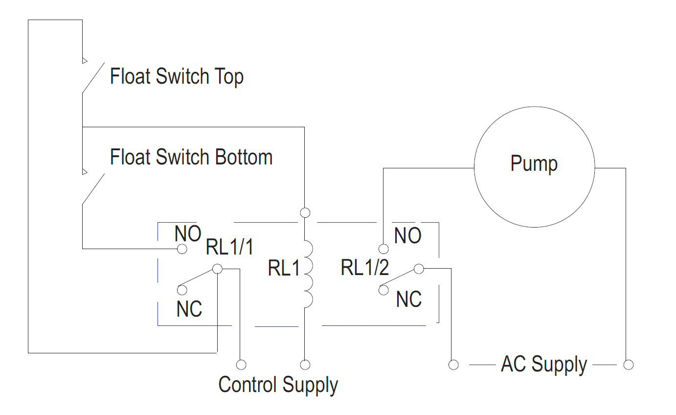
In a multi point float switch, a low alarm could trigger the led light to turn on and send a signal to turn on an automatic water pump to refill the water back to the preprogrammed water level. 2 wire well pump diagrams are slightly easier to understand and are more straight forward to wire. 2 wire well pump wiring diagram.
The float switch model is linked to above. Red and yellow might indicate that it is a 2 wire 220 volt pump. I'm using a contactor because the well installers said that is the way it should be done.
Splice the wire to the motor leads. A wiring diagram is normally found on the inside of the cover. The information below refers to v pumps and wiring.
It's a 3/4 hp submersible pump that they have wired using 10 gauge wire. As the liquid level goes up or down, it moves vertically with the liquid level. The float switch moves with the water level in the tank and this determines when the pump turns on please note:
Submersible well pump wiring diagram. How single point & multi point switches work. Float switch installation wiring and control diagrams apg for 3 wire submersible pump wiring diagram by admin from the thousand images on line about 3 wire submersible pump wiring diagram selects the top selections having ideal quality just for you all and this photographs is one among graphics libraries in your best pictures gallery concerning 3 wire submersible.

Septic Pump Wiring Diagram Free Wiring Diagram
2 Wire Well Pump Wiring Diagram easywiring

Mesa De Centro Redonda Ikea Uk redondas [Download 18
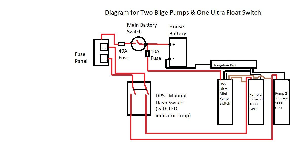
Two Bilge Pumps, One Ultra Float Switch Wiring Diagram

2 Wire Submersible Well Pump Wiring Diagram Wiring

Water Pump Control Panel Wiring Diagram Wiring Diagram

[DIAGRAM] Wiring Diagram For Float Switches FULL Version

Single Ball Float Switch Wiring Diagram Bosch Dishwasher
Everbilt Piggy Back Float Switch For Sump And Sewage Pumps

Septic Tank Float Switch Wiring Diagram Wiring Schema
I'm looking to hook up a well pump to turn on by a float

Rule Bilge Pump Wiring Diagram / Diagram Rule Bilge Pump


Dual Float Switch Wiring Diagram For Your Needs

Lead Lag Pump Control Wiring Diagram Free Wiring Diagram
Bilge Pump Float Switch Wiring Diagram Cadician's Blog

3 Wire Float Switch Wiring Diagram easywiring

Septic Pump Float Switch Wiring Diagram Free Wiring Diagram
Wiring Diagram Float Switch 6

230v Float Switch Wiring Diagram